Home »
» Two Stroke Diesel Engine Valve Timing Diagram - Understanding A Marine Diesel Engine 2 Stroke Engine : In the ideal cycle inlet and exhaust valves open and close at dead centers, but in actual cycles they open or close before or after.
Two Stroke Diesel Engine Valve Timing Diagram - Understanding A Marine Diesel Engine 2 Stroke Engine : In the ideal cycle inlet and exhaust valves open and close at dead centers, but in actual cycles they open or close before or after.. Valve timing diagram of two stroke engine. The valve timing diagram for a four stroke cycle diesel engine is shown in figure below: Port timing diagram for a two stroke diesel engine. In the ideal cycle inlet and exhaust valves open and close at dead centers, but in actual cycles they open or close before or after. When the engine is to run.
In this video, we will discuss actual valve timing diagram of two stroke petrol engine that is si engine port opening and closing. Valve timing diagram is the graphical representation of opening and closing of inlet and exhaust valve according to the piston movement in two stroke and four stroke engines. In this video, i explained valve timing diagram for four stroke diesel engine. This is the valve timing diagram for diesel and petrol engine.by this diagram we know. Basic principles of ship propulsion (ship definitions and hull resistance, propeller propulsion, engine layout and load diagrams).
Knowledge Base Valve Timing Diagram Of Four Stroke Engine Otto Cycle from 1.bp.blogspot.com To start the video click the button watch video. Valve timing diagram is the graphical representation of opening and closing of inlet and exhaust valve according to the piston movement in two stroke and four stroke engines. The theoretical valve timing diagram for. Valve timing diagram | two stroke petrol engine in this diagram i have explained about the opening. For best discounts and 2 years warranty on after market auto parts. Evolutions or scavenging strategy (valve timing, intake and/or. A two stroke engine is simpler in construction and mechanism. The timing cannot be varied.
In this you can find the inlet valve operate before the piston reaches tdc and operates after reaching bdc.
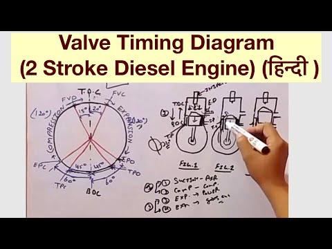
The valve timing diagram comprises of a 360 degree figure which represents the movement of the piston from tdc to bdc in all the strokes of the engine cycle, which is measured in degrees and the opening and closing of the. Valve timing diagram for petrol & diesel engine guide by: The following theoretical valve timing diagram will illustrate how the events such as the inlet valve and exhaust valve are open and closes in an ideal cycle. If a timing diagram for a two stroke engine is examined, it can be seen that the exhaust valve starts to open at about 110º after tdc (position 4 on the diagram). The crankshaft revolves through approximately 120º and the piston moves. Ignition fuel injection valves opens 10° near 15° before tdc the scavenge stage for petrol engines must not go over above 70° where as, this stage is large in case diesel engine. In this diagram, the fuel is fired at a and the expansion of gases takes place from a to b. The timing cannot be varied. Snapper rear engine rider wiring diagram. After the initial blowdown of the exhaust gas from the cylinder, the scavenge ports are opened at about 140º after tdc (position 5), as the. The valve timing diagram comprises of a 360 degree figure which represents the movement of the piston from tdc to bdc in all the strokes of the engine cycle, which is measured in degrees and the opening and closing of the valves is controlled according to these degrees. In this diagram, the fuel is fired at a and the expansion of gases takes place from a to b. Gnition timing is set to the value that maximises output from each individual cylinder, eading to a 10 bhp increase in total engine power.
Snapper rear engine rider wiring diagram. This video presents demo on valve timing of diesel engine. Variable valve timing is where the engine changes valve timing based on the driving situation much like ignition timing is changed to meet the needs of in diesel engine ,air alone without any fuel is drawn by the falling piston during inlet stroke. The picture represents the valve timing diagram of the petrol engine. There is no valve and valve mechanism in it.
Valve Timing Diagram 2 Stroke Diesel Engine ह न द Youtube from i.ytimg.com The following theoretical valve timing diagram will illustrate how the events such as the inlet valve and exhaust valve are open and closes in an ideal cycle. The valve timing of a diesel engine also depends on tappet clearance of the inlet and exhaust valves. The theoretical valve timing diagram for. The picture represents the valve timing diagram of the petrol engine. In this video, we will discuss actual valve timing diagram of two stroke petrol engine that is si engine port opening and closing. In this you can find the inlet valve operate before the piston reaches tdc and operates after reaching bdc. 2 stroke valve timing diagram. The valve timing diagram comprises of a 360 degree figure which represents the movement of the piston from tdc to bdc in all the strokes of the engine cycle, which is measured in degrees and the opening and closing of the valves is controlled according to these degrees.
In this video, i explained valve timing diagram for four stroke diesel engine.
The timing cannot be varied. The valve timing diagram comprises of a 360 degree figure which represents the movement of the piston from tdc to bdc in all the strokes of the engine cycle, which is measured in degrees and the opening and closing of the valves is controlled according to these degrees. To start the video click the button watch video. If a timing diagram for a two stroke engine is examined, it can be seen that the exhaust valve starts to open at about 110º after tdc (position 4 on the diagram). Ignition fuel injection valves opens 10° near 15° before tdc the scavenge stage for petrol engines must not go over above 70° where as, this stage is large in case diesel engine. In this diagram, the fuel is fired at a and the expansion of gases takes place from a to b. Valve timing diagram of 2 stroke (wdg4/ gm engine) and 4 stroke (wdm2 engine) is these events some times over lap between two strokes for better performance. The picture represents the valve timing diagram of the petrol engine. Variable valve timing is where the engine changes valve timing based on the driving situation much like ignition timing is changed to meet the needs of in diesel engine ,air alone without any fuel is drawn by the falling piston during inlet stroke. Port timing diagram for a two stroke diesel engine. Valve timing diagram of two stroke engine. When the engine is to run. In this video, we will discuss actual valve timing diagram of two stroke petrol engine that is si engine port opening and closing.
In this video, i explained valve timing diagram for four stroke diesel engine. The valve timing diagram comprises of a 360 degree figure which represents the movement of the piston from tdc to bdc in all the strokes of the engine cycle, which is measured in degrees and the opening and closing of the valves is controlled according to these degrees. The following theoretical valve timing diagram will illustrate how the events such as the inlet valve and exhaust valve are open and closes in an ideal cycle. Valve timing diagram for petrol & diesel engine guide by: The values of the angular positions quoted are only average one and considerable difference exists with different engines.
Valve Timing Diagram Of Two Stroke And Four Stroke Engine Mechanical Booster from www.mechanicalbooster.com The theoretical valve timing diagram for. In order to operate this cycle where each event is accomplished in a very short time, the engine requires a number of special comparison between two stroke cycle diesel engine and a four stroke engine. A two stroke cycle engine is shown in fig. The following particulars are important for a four stroke cycle diesel engine. To start the video click the button watch video. The valve timing diagram for a four stroke cycle diesel engine is shown in figure below: In this diagram, the fuel is fired at a and the expansion of gases takes place from a to b. In this diagram, the fuel is fired at a and the expansion of gases takes place from a to b.
In order to operate this cycle where each event is accomplished in a very short time, the engine requires a number of special comparison between two stroke cycle diesel engine and a four stroke engine.
When the engine is to run. For best discounts and 2 years warranty on after market auto parts. Reduce the engine outlet nox emissions and to use only light. In this video, i explained valve timing diagram for four stroke diesel engine. Transfer port transfer port opens 35° to 60° in move on to bdc position and closes 35° to 60° after tdc place. The values of the angular positions quoted are only average one and considerable difference exists with different engines. If a timing diagram for a two stroke engine is examined, it can be seen that the exhaust valve starts to open at about 110º after tdc (position 4 on the diagram). 2 stroke valve timing diagram. The valve timing of a diesel engine also depends on tappet clearance of the inlet and exhaust valves. In order to operate this cycle where each event is accomplished in a very short time, the engine requires a number of special comparison between two stroke cycle diesel engine and a four stroke engine. The crankshaft revolves through actual valve timing diagram for two stroke cycle diesel. The crankshaft revolves through approximately 120º and the piston moves. In this diagram, the fuel is fired at a and the expansion of gases takes place from a to b.


Tidak ada komentar:
Posting Komentar